![<?echo $_SERVER['SERVER_NAME'];?>](/template/twentyseventeen/skin/images/header.jpg)
Thermal power generation facilities have proven to be a stable and reliable source of energy for over a hundred years, but these facilities are huge and complex, and the cost of construction is on the rise. At the same time, operating these facilities with minimal carbon emissions and environmental impact standards also faces significant challenges and cost pressures. In contrast, modern photovoltaic (PV) power systems are a reasonable alternative to thermal power plants that can provide lower long-term operating costs, modular scalability and more efficient, with lower carbon emissions than centralized power plants a lot of.
Photovoltaic power generation systems consist of multiple components such as photovoltaic panels that convert light energy into electricity, mechanical and electrical connectors, accessories, and solar inverters that are essential to transporting solar-generated electricity to the grid.
What is a solar photovoltaic inverter?
Photovoltaic panels convert sunlight into direct current, and in order to minimize line losses and transmit electrical energy over longer distances, direct current must be converted into high voltage alternating current. Solar PV inverter can achieve the above DC to AC conversion, is the most critical part of all photovoltaic power generation system. However, this is only one of the key features of a PV inverter.
Photovoltaic inverters also have a grid disconnect capability that prevents the photovoltaic system from providing power to the unconnected public service system; that is, if the inverter remains online during a grid disconnect or is in an unreliable connection When power is supplied, it causes the PV system to feed the transformer in the local public service system and generate several thousand volts on the public service system wiring, which will jeopardize the safety of public service equipment operators. Safety Standards Regulations IEEE1547 and UL1741 states that the inverter connected to the grid must be disconnected when AC voltage or frequency exceeds specification limits or must be switched off completely when the grid is no longer present. When reconnected, the inverter can not transmit power immediately and needs to wait until the inverter detects a rated utility service voltage and frequency for more than five minutes. Of course, the responsibility of the inverter more than that.
The inverter is also used to compensate for the environmental factors that affect the output of the power. For example, the output voltage and current of photovoltaic panels are highly sensitive to changes in temperature and light intensity (also referred to as "light intensity") per unit area. The output voltage of the battery is inversely proportional to the battery temperature, and the battery current is proportional to the light intensity. These changes with other key parameters lead to significant shifts in the optimum inverter voltage / current operating point. The frequency converter solves this problem by using closed-loop control to maintain the so-called maximum power point (MPP), where the product of voltage and current is maximized. In addition, the inverter supports manual and automatic input / output disconnect during service operations, EMI / RFI conduction and radiation suppression, ground fault interrupts, PC-compatible communication interfaces and more . The inverter is housed in a sturdy box that can be operated outdoors for 25 years at full power. This is really not a feat!
Detailed introduction
As shown in Figure 1, a single-phase photovoltaic inverter uses a digital power controller and a pair of high-side / low-side gate drivers to drive a pulse width modulated (PWM) full bridge converter . The full bridge topology is commonly used in inverter applications because it is the highest load carrying capacity in any switch mode topology. Referring to FIG. 1A, the PWM voltage switch effect produces a discrete (albeit somewhat noisy) 60 Hz current waveform at the full bridge output. The high-frequency noise is partially filtered and produces the appropriate low-amplitude 60Hz sine wave, as shown in Figure 1B. The filtered waveform is transmitted through an output transformer that has three functions: 1) to further smooth the AC waveform; 2) to modulate the voltage amplitude to meet specific grid requirements; and 3) to electrically isolate the DC input of the inverter from the high-voltage AC grid.
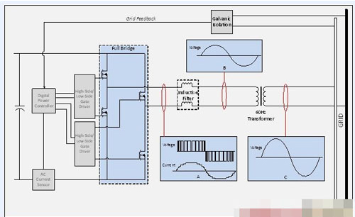
Figure 1: Single-stage, single-phase inverter block diagram
Photovoltaic inverter design needs full trade-off, if the trade-off error, may make designers suffer. For example, PV systems need to operate reliably with a full rated output of more than 25 years and a competitive price, so designers need to weigh cost / reliability. Photovoltaic power generation systems use high-efficiency inverters because high-efficiency inverters operate at lower temperatures and longer durations than low-efficiency inverters, and can save photovoltaic system system manufacturers and users more money.
Endless pursuit of higher efficiency Inverter requires more design trade-off, which will affect the choice of components (mainly door drivers, power switches and magnetic components such as transformers); PCB construction and inverter package Heat demand. The PV panel's output voltage also varies with the degree of exposure to sunlight, so it is useful to have the inverter input voltage range adapted to the PV panel's output voltage range. This, in turn, will create more design trade-offs that further affect the complexity, cost, and efficiency of the system, which is just the hardware part. Now let's take a look at the control aspects.
The inverter's "brain" is a controller, usually a digital power controller (DPC) or a digital signal processor (DSP). In general, the controller's firmware is implemented using the state machine approach, which is the most efficient way to implement uninterrupted (failed) code to prevent execution from inadvertently entering an infinite loop. Firmware execution is hierarchical, serving higher priority functions than lower priority functions more frequently. In PV inverters, isolation feedback loop compensation and power switching modulation are usually given the highest priority, followed by circuit protection functions that support the UL1741 and IEEE1547 safety standards, followed by efficiency control (MPP). Most of the remaining firmware is optimized for operation at the point of presence, monitoring of system operation, and support for system communications.
Photovoltaic inverters To work 25 years in high temperature and / or cold, we pay special attention when choosing components for inverters. Obviously, some components, such as electrolytic capacitors used for filtering and optocouplers used for opto-isolation, can not have 25 years of life. Electrolytic capacitor will dry up and dried up, LED optocoupler brightness will gradually dim until stopped. The solution to these fragile components is to replace them with high quality film capacitors (for higher reliability but at higher cost). The best long-term solution is to abandon optocouplers and use advanced CMOS process isolation components.
CMOS process technology offers high reliability, low cost, high speed, small size, low power consumption, operational stability in the extreme voltage and temperature range, and many other features that are worth having. Unlike the gallium arsenide (GaAs) process used in optocouplers, which is fabricated using a CMOS process
3T Mining Loader,3 Ton Mine Loaders,Wheel Mine Wheel Loader,3 Ton Wheel Mine Wheel Loader
Taian zhengtai construction machinery Co., Ltd , https://www.taztmachine.com