![<?echo $_SERVER['SERVER_NAME'];?>](/template/twentyseventeen/skin/images/header.jpg)
1. How to determine the capacity of the physical detection device coal bucket?
A: Obtained by multiplying the maximum coal transported per hour by 2% on coal conveyor belts.
For example, the maximum coal transmission capacity of a coal conveyor belt is 1000t/h, and the capacity of a coal hopper with a physical detection device is 20t. However, it cannot be just a conclusion, but also refer to other indicators.
2. Why is the device's maximum capacity Dmax defined as It≤Dmax≤100t?
Answer: The weighing coal feeder transport volume is 50t/h. The physical detection device that produces It can solve the problem of physical verification.
So, the lower limit is lt. 100t is considering that the capacity of thermal power plants will continue to increase. From the current point of view, 3000t/h is very large. Physical inspection can be carried out according to a 60-ton device prescribed by the Ministry of Electric Power. However, the upper limit is limited to 100 tons in order to allow for continued improvement.
3. Why is the determination of the display division value: 0.1kg≤Dmax~≤10kg?
A: The range of display division values ​​is considered to be 1/1000 of the maximum weighing range. Generally, it is sufficient to meet the requirement of sufficient display digits for the inspection. D must equal the following values ​​expressed in mass units kg: 1x10k, 2x10k, 5x10k, k is a positive integer, negative integer or zero.
However, for the current production technology in China, d generally takes 1 and if 0.5 is taken, its stability is difficult to guarantee.
4. Why must the number of inspection divisions be greater than 3000?
The number of test divisions is the key to determine the relative use of physical detection devices, the number of the most important.
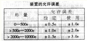
5. What are the types of errors allowed for the device?
A: It is divided into the verification error and the use of error. How does the measurement management form?
Answer: It consists of formal approval, first verification, subsequent verification, (such as periodic verification) and inspection in use.
7. Verification items and verification methods A: 1) Zero stability steps:
I will automatically adjust the zero point and track must be out of operation. Use manual zeroing during the test to make the display zero.
II Continuously open and close the hopper door for one, two or three times. The change of the zero point indication should not exceed 0.5e.
Follow-up zero checks are conducted in this way.
In addition, when d=e/5, the rounding error is also determined using a small weight equivalent to 0.1e. Each time a small weight of 0.1e is placed on the weighing to determine the rounding error. Each time a weight of 0.1e is added to the weighing hopper, until the display increases by 0.2e, the rounding error of the indication value is calculated as follows:
E=1+e/10-â–³mm
Where E: rounding error for each firm result I: each time the standard load display value Δm is added: the indication value “transition point†is added, the cumulative value of small weights m: the standard for each test addition Load e: verification indexing value 2) Drift and zero-back variation during maximum weighing
After the zero stability check is made, zero it again and measure a zero again.
II Add the maximum weighing load, record the displayed value, then static pressure for 30 minutes, observe once every 5 minutes.
3) Indications and repeat steps for each weighing point:
I choice of weighing point:
Must include: a) Empty scale, maximum weighing point.
b) The interval between weighing points should be 0. IDmax-0.2Dmax, no less than five points.
II. The load must be monotonically increasing or decrementing when measuring the load. III. The verification of the accuracy of the indications for each of the three process and return weighing points shall be performed. The verification result requires that the indication error of each weighing point should not be greater than the allowable error of the inspection.
IV compares the repeatability of each weighing point during the process and the backhaul, respectively. That is, the difference between the maximum indication value and the minimum indication value cannot exceed the allowable error of the timing for each weighing point.
V should be re-zeroed every time a process test is performed, but the zero auto tracking function should exit.
4) Overload test Perform overload test after verification of indication accuracy.
step:
I plus 1.25Dmax weighing load, static pressure 30min, parts should be no damage.
II Remove all the load and perform zeroing again. Then perform a test of maximum load accuracy.
5 partial load verification steps:
The I load test load is about 1/10 of the maximum capacity.
II Test the #1, #2, #3, and #4 corners, respectively.
6) Discriminating power verification The verification power is based on the requirements of the verification division value e. The weight is 1.4e. Therefore, the indication value can be clearly observed as long as it is placed directly and the correction error is not found. Is there an e-change above.
step:
When verifying the empty weigh and maximum weighing, the identification value shall be verified after the value to be displayed is stable.
The amount of II code added is 1.4e. The original indication should have a change of more than e.
7) Anti-interference performance test A. Power voltage fluctuation test procedure:
I adjusts to be empty when the zero point II empty calls the power voltage from 220v → 187v
220v→242v
III80% Dmax time and space when the power supply voltage is 220v → 187v
220v→242v
B. Grid interference steps:
I in the display system power supply with the network access> 500W impact drill II empty weighing power supply voltage from 220v → 187v
220v→242v
III80% Dmax time and space when the power supply voltage is 220v → 187v
220v→242v
8) Safety Performance Test Procedure:
I Disconnect external power supply II Short-circuit the display power supply III Take a megohmmeter of 500V. After the pressure is applied to the weighing hopper and the ground terminal for Imin, read the resistance value.
8. What can be reduced by reducing the number of test items?
I. The newly installed and repaired electronic belt scale physical detection device shall be tested for all items.
The test of the period of cycle II may not be carried out for 16, 19 or 22 tests.
9. How to deal with the verification result?
The device that has passed the test is issued with a certificate for verification, and the device that has failed the test is issued a notice of the result of the verification. The data in the verification results should be revised to 0.1e.
10. How much is the verification period?
The verification period of the device is one year. If the annual stability of the device is unqualified, the verification cycle should be shortened to six months.
Water Source Heat Pump
Cooling capacity: 10kW-130kW.
Characteristics
1.Panels and frame are made from galvanized steel protected with polyester powder painting to ensure total resistance to atmospheric agents.
2.Hermetic compressor. Single phase (mod. 10, 12,15) and 3-phase (mod.17 to 130) scroll type compressors, with built-in thermal overload cut-out and crankcase heater, mounted on rubber vibration dampers.
3.Evaporator. High efficiency plate type heat exchanger, factory insulated with flexible close cell material.
4.Condenser. High efficiency plate type heat exchanger, factory insulated with flexible close cell material.
5.Desuperheater High efficiency stainless steel brazed plate heat exchanger, factory insulated with flexible close cell material.
6. Refrigerant circuit. Copper tube connection with charge valves, filter drier, thermostatic expansion valve (capillary for mod.10 to 15), gas-liquid separator, high pressure switch and low pressure switch. The heat pump units are complete also with 4-way valve and one way valve.
7.Hydraulic circuit. Built with user side and source side water inlet/outlet connectors, water discharge connectors, air vent valve (mod.10 to 30 the user side is complete also with expansion vessel, water pump and flow switch. )
8. Electric panel. Consists of:
♦ Compressor contactor
♦ Compressor protection breaker
♦ User side water pump contactor (for mod.10 to 30)
♦ User side water pump breaker (for mod.10 to 30)
♦ Microprocessor with function display
9.Optional
♦ Sight glass which must be installed in factory
♦ Source side flow switch
♦ Source side water pump
♦ Anti-vibration rubber
♦ Metallic filter for the water circuit
♦ Heat recovery exchanger
♦ Tube in tube heat exchanger


Water Source Heat Pump
Water Source Heat Pump,Water Source Heat Pump Unit,Packaged Water Source Heat Pump,DG Heating Cooling System
Jinan Amrta Air Conditioning Co.,Ltd , http://www.amrtaac.com