To some extent it can be said that the accuracy of the machine tool depends mainly on the accuracy of the detection elements in the closed-loop control system.
Example 1 When the horizontal machining center of the Siemens 8M system was running normally, the machine tool suddenly stopped working. The CRT had an NC alarm 104. The operator turned off the power and started the alarm. The alarm was removed and normal operation resumed. After several ten minutes, the fault recurred.
Inquire NC104 alarm, expressed as: X-axis measurement of closed-loop cable broken short circuit, signal loss, incorrect threshold signal frequency signal is incorrect. The X, Y, and Z axes of the machine tool use a linear ruler to detect the position of the machine tool, and perform feedback control to form a closed-loop system.
As a rule of thumb, if the test element is contaminated by dirt and oil, it sends a false signal. Check that the reading head and scale are not contaminated by oil and dust. Then check the differential amplifier and measurement circuit board. No adverse events were found after these operations. We focused on the feedback cable and measured the feedback terminals. We found line 13 voltage was unstable. After the power outage, it was found that with a large change in the cable swing resistance, it was found that this line would follow the movement of the rail in the X axis. Non-connected, causing the feedback value to be unstable, causing the motor to lose synchronization. After wiring, the fault is eliminated.
Example 2 A vertical machining center supporting FAGOR 8030. When the reference point is approached, the reference point position is unstable. Reference point faults with poor positioning accuracy.
As a rule of thumb, the main cause of pulse encoder synchronization error is the encoder zero pulse fault or reference reference speed is too low. Since the oscilloscope is required to check the zero point pulse of the reference point, it is generally possible to first check the setting of the reference speed and position gain, and confirm that the position following error value of the system is above 1281xm.
If the parameters are set correctly, the possible reason is that the "zero pulse" signal is bad. Because the signal pulse width of the zero pulse is narrow, it is very sensitive to interference, so it must be checked for the following aspects:
The first is that the supply voltage of the encoder must be in the range of +5V+O.2V. When less than 4.75V, it will cause "zero pulse" output disturbance. Secondly, the shield of the encoder feedback must be reliably connected, and the position feedback cable should be as far away as possible from the interference source and power line. In addition, the "zero pulse" output of the encoder itself must be correct to meet the system's requirement for a zero pulse.
After checking that the machine tool works normally in manual mode, the reference point deceleration speed and position loop gain are set correctly, and the +5V voltage of the measurement encoder is normal, and the process of returning to the reference point is correct. The initial determination of the fault is caused by the disturbance of the encoder zero pulse. The inspection found that the shielded cable of the shaft encoder connection cable was detached. After connection, the positioning accuracy reached the original machine requirements.
Frequently asked beginners, why do CNC machine tools have to go back to the reference point? Isn't it not possible to go back to the reference point? Simply speaking, the purpose of the reference point is to create a unique coordinate system on the machine after each power-on. Because after the machine has finished turning off the power. The CNC system loses its memory of each coordinate position. After turning on the power, it is necessary to return each coordinate to a fixed position of the machine tool, that is, the zero point or origin of the coordinate system, which is also referred to as a reference point or a machine tool reference point. The reference point operation will directly affect the normal operation of CNC machine tools.
Our company is a professional manufacturer and exporter of a variety of handicrafts. Our company has been highly commented and trusted by the worldwide business partners for the diversity and high quality of our distinctive products in the past years.
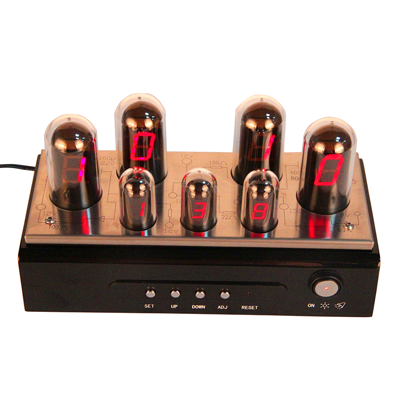
The main material of our metal digital clock is Metal+ABS+electronic components. It is without battery. Metal digital clock is with adapter supported. The time is much preciser and very easy to read. The metal digital desk clock is very popular in the young people and gadget lovers.
Our business principle is "quality good, favorable price, timely delivery and top service".

Metal Digital Clock,Digital Clock Desktop,Modern Metal Digital Clock,Clock Silver
Guangzhou Huan Yu Clocking Technologies Co., Ltd. , https://www.mk-times.com
![<?echo $_SERVER['SERVER_NAME'];?>](/template/twentyseventeen/skin/images/header.jpg)