![<?echo $_SERVER['SERVER_NAME'];?>](/template/twentyseventeen/skin/images/header.jpg)
Abstract : This paper discusses the communication problems in the automation of distribution networks, and focuses on optical fiber networks (optical networks with large networks, fiber optic ring networks), field buses (LonWorks, PROFIBUS, CAN), new digital power line carriers (NDLC), etc. A variety of distribution network automation commonly used communication methods, combined with distribution network automation engineering reality, summed up a variety of solutions Sifang Huaneng CSDA2000 distribution network automation system.
With the rapid development of the power industry, users are increasingly demanding the reliability of power supply. Distribution network automation has become a new hot spot in the field of power system automation in China, and is an important stage in the development of the power industry. To realize the automation of distribution network, the key lies in communication. The selection of communication method should be suitable for the current situation of distribution network in China and the actual situation of users. At present, the main communication methods include optical fiber, field bus and carrier wave. This article can provide a reference for the majority of users concerned with communication problems in the distribution network automation.
1 Overall structure of distribution network communication network Figure 1 describes the overall structure of distribution automation. Distribution automation network communication system is an inseparable part. In order to implement the principle of function decentralization, hierarchical stratification, and improving the speed of accident response, distribution automation systems are generally divided into three levels: main stations, substations, and feeders. According to the size of the distribution network, the main station layer can be further divided into the main station and the regional station.
Between the main station and the substation, the information volume is large, and a high-speed and reliable communication channel is required. However, due to the small number of nodes, optical fiber Ethernet or fiber ring network is generally used at present, and the cost of the two kinds of optical fiber communication methods is similar. Although the optical fiber ring network is more mature, but the optical fiber Ethernet is the main direction of development, optical fiber Ethernet technology and related equipment have been tested in practice, is being promoted and applied.
Substations and feeder communication networks are generally considered in a unified manner. The structure of feeder networks is complex, and the situation is diverse. The characteristics of different locations are different, and it is difficult to find a unified communication mode. At present, a variety of communication methods such as optical fiber, twisted pair, power line chopper, and wireless are commonly used. The common structure is: building a trunk communication network with fiber; using a fieldbus technology (such as LonWorks, CAN, PROFIBUS) or RS485 through a twisted pair, connecting the trunk TTU, the FTU/TTU of the branch line to the trunk FTU, and passing High-speed Fibre Channel uploads information to the substations and the master station. The trunk FFU should have such a centralized forwarding capability.
The feeder communication network can also use the same optical fiber Ethernet or fiber ring network as the two kinds of optical fiber communication methods. According to their different performance and characteristics, to meet different needs of use.
The 10kV power line carrier is also a kind of communication means worthy of attention on feeders, and it is particularly suitable for long branch lines in urban and rural areas.
For low-voltage (220/380V) meter reading systems, power line carrier meter reading is the best method, and its performance and price ratio is the highest. Low-voltage power line carrier meter reading is commonly used in the following two modes: one is for a centralized 10 to 30 pulse meter equipped with a meter reader, the meter reader is connected to the concentrator at the distribution transformer through a low-voltage power line carrier; In each meter, a carrier module is added and the carrier module is directly connected to the concentrator. The former is more economical, but requires relatively concentrated electricity meters; the latter is relatively expensive, but it applies to the spread of electricity meters.
The concentrators are generally placed at the distribution transformers, one for each station, and the concentrators can also be combined with the TTU.
The main communication methods of distribution automation include DLC, optical fiber, telephone, twisted pair, and wireless. Their functions are shown in Table 1.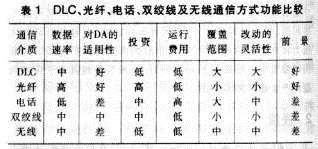
In addition to the typical structure of the system, there are other configurations depending on the actual situation. The following lists several different configurations.
(1) The FTU unit is directly connected to the communication system and does not need to be connected through substations. The specific connection method is shown in Fig. 2 (the same part as the typical configuration is abbreviated, only the different connections are described, and the following figures are the same).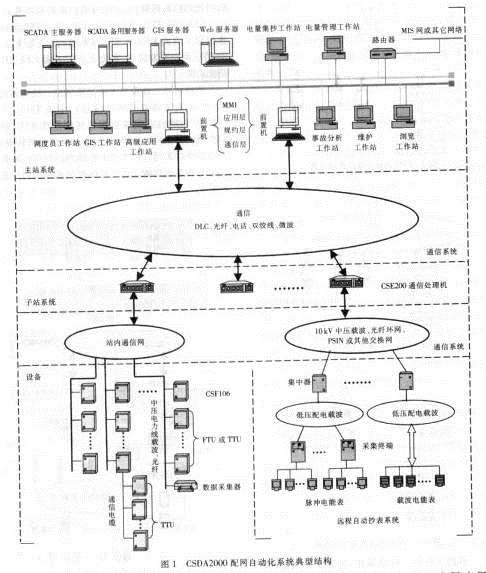
(2) The meter reading system is connected with the communication system through the FTU, not through the sub-station and the communication system. The specific connection method is shown in FIG. 3 .
(3) The meter reading system is directly connected to the master station system through a communication processor. The specific connection method is shown in Figure 4.
The above only enumerates the typical structures of several systems of the company's products. In actual use, it can be modified and adjusted according to the specific conditions such as the scale of the distribution network and the environment to meet the needs of practical applications.
2 Distribution network automation system several kinds of main communication ways 2.1 Optical fiber communication 2.1.1 Application of optical fiber ring network in distribution network automation In the distribution automation system, the optical fiber network that has been used more often is a ring network. Its structure is simple and reliable. The optical fiber self-healing ring network communication method is adopted, and the network is formed by connecting each node in two-way closed-loop series. Normally, the other ring of the first ring works. If one of the optical fibers is disconnected due to accidents such as construction, the self-healing function of the optical fiber dual ring network can be used to maintain the communication. Therefore, this communication is very High reliability.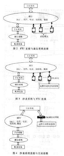 The optical fiber ring network distribution automation implementation scheme is as follows:
(1) The single-mode optical fiber is used between the master station and the substation, and is connected in a fiber-optic Ethernet mode. The communication rate is 100Mbps, and 2 pairs of optical fiber conversion modules are required (2 substations);
(2) Single-mode optical fibers are used between the sub-stations and the trunk network cabinets, switching stations, and FTUs, and dual-ring communication with self-healing functions is implemented through optical fiber dual-loop connections (using single-mode dual-transmit, dual-receive optical modems);
(3) Trunk TTU, Trunk FTU, and TTU are connected to the FTU of the trunk through a twisted pair cable. The LONWORKS fieldbus protocol is adopted. The FTU centrally forwards information. The FTU product CSF101 of the company has this function.
The equipment on the terminating ring exchanges information with the substations. The rings exchange information through the master station-substation fiber optic Ethernet. Trunk TTUs, branch lines FTUs and TTUs are connected to trunk FTUs through twisted pair cables and enter the communication network. For a substation, the information within the substation is obtained through the local station ring network and the master station-substation optical Ethernet to complete the distribution automation function. The schematic diagram of the fiber ring network distribution system communication is shown in Figure 5.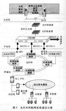 2.1.2 Application of Fiber Ethernet in Distribution Network Automation Fiber-optic Ethernet is flexible, high-speed, and has rich technical resources. Some fiber-optic ring networks are difficult to solve and can only be solved using fiber-optic Ethernet. For example, the FTU range managed by sub-stations. When some changes occur, some FTUs belong to the A substation management. The A substation is responsible for communicating with it. After the operating mode changes, it becomes the substation B management, and the substation B is responsible for communicating with it. In this case, the fiber ring The network cannot handle; for example, the feeder protection function requires that FTUs and substations exchange information quickly (within 100 Mbps) between FTUs. Only optical Ethernet can meet this requirement.
The fiber optic Ethernet distribution automation scheme is as follows:
(1) The single-mode optical fiber is used between the master station and the substation, and is connected in a fiber-optic Ethernet mode. The communication rate is 100Mbps, and 2 pairs of optical fiber conversion modules are required (2 substations);
(2) Fiber optics are used between the sub-stations and trunk line ring network cabinets, opening and closing stations, and FTUs. Communication processors CSE200 and network switches are used. Fiber-optic communication is performed between the network switches and the backbone FTUs. Smart fiber is installed in the FTUs. Interface; through the CSE200 to complete RTU access to the substation, GPS access to local maintenance or remote transmission, electronic equipment access and other functions;
(3) Main line TTU, branch line FTU, and TTU are connected to the trunk line FTU through the twisted pair. The LonWorks field bus protocol is used to forward information centrally by the FTU. The FTU product CSF101 of this company has this function. Figure 6 shows the communication diagram of the optical fiber Ethernet distribution system.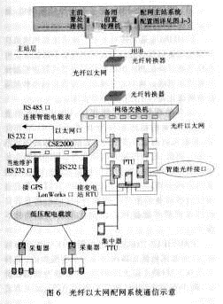
2.2 Fieldbus 2.2.1 LonWorks Fieldbus Network LonWorks is another field bus technology with strong strength. It was launched by Echelon Corporation of the United States and initiated by it together with Motorola and Toshiba, and was officially announced in 1990.
Network communication design is simplified to parameter settings through network variables. The communication rate varies from 300bps to 1.5Mbps, and the direct communication distance can reach 2.7km (78kbps, twisted pair); twisted pair, coaxial cable, and optical fiber are supported. , RF, infrared, power lines and other communication media, and the development of the corresponding intrinsically safe explosion-proof products, known as the general control network.
The konTalk protocol used by LonWorks technology is encapsulated in a so-called Neuron chip. There are three 8-bit CPUs in the integrated chip. The first one is used to complete the functions of Layer 1 and Layer 2 in the open interconnect model. It is called media access processor to implement media access control and processing; Complete the functions of the 3rd to the 6th layer, called the network processor, to perform addressing, processing, background diagnosis, path selection, software timing, network management and network communication control, send and receive data packets, etc. of the network variables; the third is The application processor executes operating system services and user code.
The neuron chip also has a storage information buffer to enable the transfer of information between CPUs and as network buffers and application buffers. Echelon's technology strategy is to encourage each OEM developer to use the LonMARK Interoperability Association to develop and promote LonWorks technology and products. It has been widely used in building automation, home automation, security systems and other industries. In addition, LonWorks neuron chips also have unique advantages in the development of intelligent communication interfaces and smart sensors.
The following is a brief introduction to the technical performance of the LonWorks network, the connection method and its application in feeder automation.
2.2.1.1 Network Technology Performance LonWorks is a real-time measurement and control network developed by Echelon Corporation in the United States. Its main features are as follows:
(1) Adopt the Lontalk communication protocol, which follows the full 7-layer model of the open system interconnection OSI defined by the International Organization for Standardization (ISO). The network protocol is open and interoperability can be achieved.
(2) Can communicate in any medium, including twisted pair, power line, optical fiber, coaxial cable, etc., a variety of media can be mixed in the same network;
(3) The network operating system structure can be master-slave, peer-to-peer, and client/service architectures;
(4) To provide bus topology, star topology, ring topology and hybrid topology;
(5) Improved Carrier Sense Multiple Access (CSMA), using a new CSMA with collision avoidance algorithm, which minimizes media access delay when the load is light, and minimizes the possibility of collisions when the load is heavy. ;
(6) The network communication uses the object-oriented design method, LonWorks technology calls it "the network variable", has saved the massive design workload, simultaneously has increased the communication reliability;
(7) The main component of the network is the neuron chip, which was produced by two major IC chip makers, Motorola and Toshiba.
Table 2 lists the key indicators of LonWorks using twisted pair with isolation transformer drivers.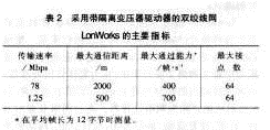
At present, the LonWorks network already has nearly 3,000 company users in the world, covering all walks of life. By the end of 1998, nearly 10 million LonWork network nodes were expected to operate in various systems.
2.2.1.2 LonWorks Network Connection Mode From the network point of view, each node connected to the network should include three parts (as shown in Figure 7): 1 The functional part of this node, such as FTU, TTU, etc.; 2 neuron chip, which is the interface for the node to exchange information with the network; 3 network driver, used to drive the channel media, such as fiber drives, twisted-pair drives.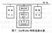
2.2.1.3 Application of konWorks Network in Feeder Automation Because LonWorks network adopts measures such as configuring 1.5kV DC isolation transformer isolation and other suitable for industrial field environment, it has strong anti-interference and anti-vibration performance and is applicable to The large temperature range is suitable for harsh industrial environments and outdoor environments. No erroneous response to the LonWorks network due to interference has occurred so far.
The bus-type carrier-sense multiple-access/collision detection (CSMA/CD) protocol uses an important message plus priority method for radial operation of feeder automation systems.
In the ISO 7 layer specification, 6 layers are solidified, which reduces the amount of secondary development work and improves reliability.
According to theoretical calculations, experiments and field verification, the LonWorks field measurement and control network fully meets the requirements for the transmission speed of feeder automation systems.
The LONWORKS network is particularly suitable for connections between FTUs on the branch line, TTUs, and FTUs on the backbone line, and connections between trunk TTUs and neighboring FTUs. The company has taken the lead in applying LonWorks technology to feeder automation.
2.2.2 PROFIBUS
PROFIBUS is an international, open, field bus standard that does not rely on equipment manufacturers. Widely used in manufacturing automation, process automation and other areas of buildings, transportation and power automation systems. PROFIBUS consists of the following 3 compatible parts, as described below.
(1) PROFIBUS-DP: It is a kind of high-speed low-cost communication, which is used for communication between equipment-level control system and distributed I/O, and can replace 24VDC or 4-20mA signal transmission;
(2) PORFIBUS-PA: Designed specifically for process automation, sensors and actuators can be connected to a single bus and have intrinsic safety specifications;
(3) PROFIBUS-FMS: used for plant level monitoring network, is a token structure, real-time multi-master network.
PROFIBUS is a fieldbus technology used for factory automation level monitoring and field device data communication and control. The distributed digital control and field communication network can be realized from the field device floor to the workshop level monitoring, thus providing a feasible solution for the realization of the plant integrated automation and field device intelligence.
Compared with other field bus systems, the biggest advantage of PROFIBUS is that it is guaranteed by the stable international standard EN50170, and its actuality is verified by actual practice. Currently applied areas include manufacturing, process control, and automation. The PROFIBUS openness and vendor-independent communication assumptions have been implemented in over 100,000 successful applications. PROFIBUS has the support of internationally renowned manufacturers of automation technology equipment. They all have their own technical advantages and can provide a wide range of high quality new products and technical services.
The PROFIBUS protocol structure is based on the ISO 7498 international standard and uses the open system interconnection network as a reference model. There are seven layers in this model (the first layer is the physical layer, the second layer is the data link layer, the third to sixth layers are unused, and the seventh layer is the application layer). The definition is as follows.
(1) PROFIBUS-DP: Defines Layers 1 and 2 and user interfaces. Layers 3-7 are not described. The user interface specifies the user and system as well as application functions that can be called from different devices, and details the device behavior of various PROFIBUS-DP devices.
(2) PROFIBUS-FMS: Layers 1, 2, and 7 are defined. The application layer includes fieldbus information specifications and low-level interfaces. FMS includes application protocols and provides users with a wide selection of powerful communication services. The LLI coordinates different communication relationships and provides device-independent Layer 2 access interfaces.
(3) PROFIBUS-PA: PA data transmission adopts the extended PROFIBUS-DP protocol. In addition, the PA also describes the PA profile of field device behavior. According to the IEC 1158-2 standard, its intrinsic safety is ensured, and field devices can be powered via the bus. Use the connector to expand the PA network on the DP. At present, PROFIBUS has many applications in integrated automation stations. In feeder automation, there are few applications in China.
2.2.3 Control Area Network (CAN)
CAN was first introduced by Germany's BOSCH company for data communication between automotive internal measurement and execution components. Its bus specification has now been set by the ISO International Standards Organization as an international standard. Thanks to the support of Motorola, Intel, Philip, NEC and other companies, it is widely used in the field of discrete control. The CAN protocol is also based on the open system interconnection model of the International Organization for Standardization. Its model structure is only three layers, that is, only the OSI underlying physical layer, data link layer, and top-level application layer are taken. The signal transmission medium is twisted pair. Communication up to 1Mbps/40m, direct transmission distance up to 10kin/5kbps. Up to 110 devices can be connected. The signal transmission of CAN adopts the short frame structure, the effective number of bytes of each frame is 8, so the probability that the transmission time is interfered with is low. When the node is seriously wrong, it has the function of auto-off, so that other nodes and their communication on the bus are not affected, and have strong anti-interference ability. At present, CAN has application in the reception of some electric meters. In feeder automation, there are a few applications in China.
2.3 Power Line Carrier Communication 2.3.1 Next Generation Medium Voltage Digital Carrier Communication System (NDLC)
At the end of 1998, Sifang Research Institute introduced a narrowband multi-frequency NDLC technology with the core of digital signal processing (DSP) decoding technology at the international advanced level. This technology breaks through the limitations of the existing power line spread spectrum DLC in principle, has -80dB absolute level of receiving capability, uses a dedicated coupling method, has a strong network management capabilities, and fully takes into account the reliability of the NDLC It provides powerful communication support for feeder automation and automatic meter reading systems.
2.3.2 Application of power line carrier in low-voltage meter reading Low-voltage meter reading mainly adopts power line digital carrier communication. It mainly consists of the following four parts: power line (carrier channel), distribution automation system equipment (acquisition terminal, concentrator, coupling) Equipment, etc.), substation data collection substations and substation transfer links (CSEl00 series communication processors).
The low-voltage side of the distribution transformer of the community collects the user's power from the collection terminal to the concentrator through the low-voltage distribution line carrier. At the same time, the concentrator collects the various AC telemetry data of the low-voltage side of the distribution transformer on the spot and takes all the power and telemetry. Data is transmitted to substation collection substations through medium voltage power carrier. Carrier communication adopts 101 simplified stipulation, the design baud rate is 2400bps. The substation collection substation forwards the carrier data to the CSEt00 data receiving end through the RS232 serial port. After the CSEl00 receives the data, it forwards the data to the automatic meter reading background of the distribution center through the existing fiber channel. The communication protocol with the background interface is DNP3.0. .
The schematic diagram of the system connection on the distribution transformer side is shown in Fig. 8. The low-voltage carrier adopts phase-to-earth coupling. Here, all B-phase couplings are used. A total of 9 collectors were installed in the above 9 meter cabinets. Each collection g3 collects the electricity of all meters of the meter cabinet. The electrical pulse signal of the pulse meter is connected to the pulse signal input port of the collection terminal through the signal line. The collector couples all of the power figures to the B-phase low-voltage power line through the carrier transceiver. The concentrator collects the amount of power uploaded by the acquisition terminal through a low-voltage carrier, measures the telemetry of the low voltage side of the distribution transformer through TV and TA, and couples all the collected power and telemetry to a 10 kV medium voltage line through a 10 kV coupling device.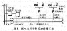
The substation side system connection is shown in Figure 9. The 10kV bus coupling phase is also the B phase (intermediate phase). The medium voltage carrier digital data passes through the coupling device and enters the data collection substation in the substation, and is then transmitted by the RS232 serial port to the CSE forwarding unit. The CSE forwards the data to the meter reading back-end interface of the distribution center through the fiber-optic remote-access DNP 3.0 protocol, thereby realizing the entire remote meter reading communication from the background to the collection terminal. The entire communication channel is a full-duplex channel. The background summoning and sending messages and the collecting terminal's initiative to send messages can be performed simultaneously.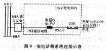
The entire remote meter reading system communication network is shown in Figure 10.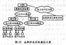 3 Conclusion Distribution automation system is generally divided into master station, substation, feeder 3 layers. According to the size of the distribution network, the main station layer can be further divided into the main station and the regional station. Between the main station and the substation, the high-speed optical fiber Ethernet scheme is preferred. Different investments are required depending on the reliability requirements. The tree structure, the single ring structure, and the double ring structure may be adopted. These three kinds of structures currently have professional manufacturers. Product support. Substations and feeder communication networks generally use a variety of communication means such as optical fiber, twisted pair, and power line carrier. The common structure is: building trunk communication network with fiber; using fieldbus technology to connect trunk TTU, FTU/TTU of branch line to trunk FTU, uploading information to substations and masters through high-speed fiber channel station. The feeder communication network adopts optical fiber communication network (optical fiber Ethernet, fiber optic ring network). The cost of these two kinds of optical fiber communication methods is similar, but the optical fiber Ethernet has more development prospects; 10kV power line carrier is also a communication method worthy of attention; power line Carrier meter reading is the best low voltage (220/380V) meter reading method.
With the rapid development of the power industry, users are increasingly demanding the reliability of power supply. Distribution network automation has become a new hot spot in the field of power system automation in China, and is an important stage in the development of the power industry. To realize the automation of distribution network, the key lies in communication. The selection of communication method should be suitable for the current situation of distribution network in China and the actual situation of users. At present, the main communication methods include optical fiber, field bus and carrier wave. This article can provide a reference for the majority of users concerned with communication problems in the distribution network automation.
1 Overall structure of distribution network communication network Figure 1 describes the overall structure of distribution automation. Distribution automation network communication system is an inseparable part. In order to implement the principle of function decentralization, hierarchical stratification, and improving the speed of accident response, distribution automation systems are generally divided into three levels: main stations, substations, and feeders. According to the size of the distribution network, the main station layer can be further divided into the main station and the regional station.
Between the main station and the substation, the information volume is large, and a high-speed and reliable communication channel is required. However, due to the small number of nodes, optical fiber Ethernet or fiber ring network is generally used at present, and the cost of the two kinds of optical fiber communication methods is similar. Although the optical fiber ring network is more mature, but the optical fiber Ethernet is the main direction of development, optical fiber Ethernet technology and related equipment have been tested in practice, is being promoted and applied.
Substations and feeder communication networks are generally considered in a unified manner. The structure of feeder networks is complex, and the situation is diverse. The characteristics of different locations are different, and it is difficult to find a unified communication mode. At present, a variety of communication methods such as optical fiber, twisted pair, power line chopper, and wireless are commonly used. The common structure is: building a trunk communication network with fiber; using a fieldbus technology (such as LonWorks, CAN, PROFIBUS) or RS485 through a twisted pair, connecting the trunk TTU, the FTU/TTU of the branch line to the trunk FTU, and passing High-speed Fibre Channel uploads information to the substations and the master station. The trunk FFU should have such a centralized forwarding capability.
The feeder communication network can also use the same optical fiber Ethernet or fiber ring network as the two kinds of optical fiber communication methods. According to their different performance and characteristics, to meet different needs of use.
The 10kV power line carrier is also a kind of communication means worthy of attention on feeders, and it is particularly suitable for long branch lines in urban and rural areas.
For low-voltage (220/380V) meter reading systems, power line carrier meter reading is the best method, and its performance and price ratio is the highest. Low-voltage power line carrier meter reading is commonly used in the following two modes: one is for a centralized 10 to 30 pulse meter equipped with a meter reader, the meter reader is connected to the concentrator at the distribution transformer through a low-voltage power line carrier; In each meter, a carrier module is added and the carrier module is directly connected to the concentrator. The former is more economical, but requires relatively concentrated electricity meters; the latter is relatively expensive, but it applies to the spread of electricity meters.
The concentrators are generally placed at the distribution transformers, one for each station, and the concentrators can also be combined with the TTU.
The main communication methods of distribution automation include DLC, optical fiber, telephone, twisted pair, and wireless. Their functions are shown in Table 1.
In addition to the typical structure of the system, there are other configurations depending on the actual situation. The following lists several different configurations.
(1) The FTU unit is directly connected to the communication system and does not need to be connected through substations. The specific connection method is shown in Fig. 2 (the same part as the typical configuration is abbreviated, only the different connections are described, and the following figures are the same).
(2) The meter reading system is connected with the communication system through the FTU, not through the sub-station and the communication system. The specific connection method is shown in FIG. 3 .
(3) The meter reading system is directly connected to the master station system through a communication processor. The specific connection method is shown in Figure 4.
The above only enumerates the typical structures of several systems of the company's products. In actual use, it can be modified and adjusted according to the specific conditions such as the scale of the distribution network and the environment to meet the needs of practical applications.
2 Distribution network automation system several kinds of main communication ways 2.1 Optical fiber communication 2.1.1 Application of optical fiber ring network in distribution network automation In the distribution automation system, the optical fiber network that has been used more often is a ring network. Its structure is simple and reliable. The optical fiber self-healing ring network communication method is adopted, and the network is formed by connecting each node in two-way closed-loop series. Normally, the other ring of the first ring works. If one of the optical fibers is disconnected due to accidents such as construction, the self-healing function of the optical fiber dual ring network can be used to maintain the communication. Therefore, this communication is very High reliability.
(1) The single-mode optical fiber is used between the master station and the substation, and is connected in a fiber-optic Ethernet mode. The communication rate is 100Mbps, and 2 pairs of optical fiber conversion modules are required (2 substations);
(2) Single-mode optical fibers are used between the sub-stations and the trunk network cabinets, switching stations, and FTUs, and dual-ring communication with self-healing functions is implemented through optical fiber dual-loop connections (using single-mode dual-transmit, dual-receive optical modems);
(3) Trunk TTU, Trunk FTU, and TTU are connected to the FTU of the trunk through a twisted pair cable. The LONWORKS fieldbus protocol is adopted. The FTU centrally forwards information. The FTU product CSF101 of the company has this function.
The equipment on the terminating ring exchanges information with the substations. The rings exchange information through the master station-substation fiber optic Ethernet. Trunk TTUs, branch lines FTUs and TTUs are connected to trunk FTUs through twisted pair cables and enter the communication network. For a substation, the information within the substation is obtained through the local station ring network and the master station-substation optical Ethernet to complete the distribution automation function. The schematic diagram of the fiber ring network distribution system communication is shown in Figure 5.
The fiber optic Ethernet distribution automation scheme is as follows:
(1) The single-mode optical fiber is used between the master station and the substation, and is connected in a fiber-optic Ethernet mode. The communication rate is 100Mbps, and 2 pairs of optical fiber conversion modules are required (2 substations);
(2) Fiber optics are used between the sub-stations and trunk line ring network cabinets, opening and closing stations, and FTUs. Communication processors CSE200 and network switches are used. Fiber-optic communication is performed between the network switches and the backbone FTUs. Smart fiber is installed in the FTUs. Interface; through the CSE200 to complete RTU access to the substation, GPS access to local maintenance or remote transmission, electronic equipment access and other functions;
(3) Main line TTU, branch line FTU, and TTU are connected to the trunk line FTU through the twisted pair. The LonWorks field bus protocol is used to forward information centrally by the FTU. The FTU product CSF101 of this company has this function. Figure 6 shows the communication diagram of the optical fiber Ethernet distribution system.
2.2 Fieldbus 2.2.1 LonWorks Fieldbus Network LonWorks is another field bus technology with strong strength. It was launched by Echelon Corporation of the United States and initiated by it together with Motorola and Toshiba, and was officially announced in 1990.
Network communication design is simplified to parameter settings through network variables. The communication rate varies from 300bps to 1.5Mbps, and the direct communication distance can reach 2.7km (78kbps, twisted pair); twisted pair, coaxial cable, and optical fiber are supported. , RF, infrared, power lines and other communication media, and the development of the corresponding intrinsically safe explosion-proof products, known as the general control network.
The konTalk protocol used by LonWorks technology is encapsulated in a so-called Neuron chip. There are three 8-bit CPUs in the integrated chip. The first one is used to complete the functions of Layer 1 and Layer 2 in the open interconnect model. It is called media access processor to implement media access control and processing; Complete the functions of the 3rd to the 6th layer, called the network processor, to perform addressing, processing, background diagnosis, path selection, software timing, network management and network communication control, send and receive data packets, etc. of the network variables; the third is The application processor executes operating system services and user code.
The neuron chip also has a storage information buffer to enable the transfer of information between CPUs and as network buffers and application buffers. Echelon's technology strategy is to encourage each OEM developer to use the LonMARK Interoperability Association to develop and promote LonWorks technology and products. It has been widely used in building automation, home automation, security systems and other industries. In addition, LonWorks neuron chips also have unique advantages in the development of intelligent communication interfaces and smart sensors.
The following is a brief introduction to the technical performance of the LonWorks network, the connection method and its application in feeder automation.
2.2.1.1 Network Technology Performance LonWorks is a real-time measurement and control network developed by Echelon Corporation in the United States. Its main features are as follows:
(1) Adopt the Lontalk communication protocol, which follows the full 7-layer model of the open system interconnection OSI defined by the International Organization for Standardization (ISO). The network protocol is open and interoperability can be achieved.
(2) Can communicate in any medium, including twisted pair, power line, optical fiber, coaxial cable, etc., a variety of media can be mixed in the same network;
(3) The network operating system structure can be master-slave, peer-to-peer, and client/service architectures;
(4) To provide bus topology, star topology, ring topology and hybrid topology;
(5) Improved Carrier Sense Multiple Access (CSMA), using a new CSMA with collision avoidance algorithm, which minimizes media access delay when the load is light, and minimizes the possibility of collisions when the load is heavy. ;
(6) The network communication uses the object-oriented design method, LonWorks technology calls it "the network variable", has saved the massive design workload, simultaneously has increased the communication reliability;
(7) The main component of the network is the neuron chip, which was produced by two major IC chip makers, Motorola and Toshiba.
Table 2 lists the key indicators of LonWorks using twisted pair with isolation transformer drivers.
At present, the LonWorks network already has nearly 3,000 company users in the world, covering all walks of life. By the end of 1998, nearly 10 million LonWork network nodes were expected to operate in various systems.
2.2.1.2 LonWorks Network Connection Mode From the network point of view, each node connected to the network should include three parts (as shown in Figure 7): 1 The functional part of this node, such as FTU, TTU, etc.; 2 neuron chip, which is the interface for the node to exchange information with the network; 3 network driver, used to drive the channel media, such as fiber drives, twisted-pair drives.
2.2.1.3 Application of konWorks Network in Feeder Automation Because LonWorks network adopts measures such as configuring 1.5kV DC isolation transformer isolation and other suitable for industrial field environment, it has strong anti-interference and anti-vibration performance and is applicable to The large temperature range is suitable for harsh industrial environments and outdoor environments. No erroneous response to the LonWorks network due to interference has occurred so far.
The bus-type carrier-sense multiple-access/collision detection (CSMA/CD) protocol uses an important message plus priority method for radial operation of feeder automation systems.
In the ISO 7 layer specification, 6 layers are solidified, which reduces the amount of secondary development work and improves reliability.
According to theoretical calculations, experiments and field verification, the LonWorks field measurement and control network fully meets the requirements for the transmission speed of feeder automation systems.
The LONWORKS network is particularly suitable for connections between FTUs on the branch line, TTUs, and FTUs on the backbone line, and connections between trunk TTUs and neighboring FTUs. The company has taken the lead in applying LonWorks technology to feeder automation.
2.2.2 PROFIBUS
PROFIBUS is an international, open, field bus standard that does not rely on equipment manufacturers. Widely used in manufacturing automation, process automation and other areas of buildings, transportation and power automation systems. PROFIBUS consists of the following 3 compatible parts, as described below.
(1) PROFIBUS-DP: It is a kind of high-speed low-cost communication, which is used for communication between equipment-level control system and distributed I/O, and can replace 24VDC or 4-20mA signal transmission;
(2) PORFIBUS-PA: Designed specifically for process automation, sensors and actuators can be connected to a single bus and have intrinsic safety specifications;
(3) PROFIBUS-FMS: used for plant level monitoring network, is a token structure, real-time multi-master network.
PROFIBUS is a fieldbus technology used for factory automation level monitoring and field device data communication and control. The distributed digital control and field communication network can be realized from the field device floor to the workshop level monitoring, thus providing a feasible solution for the realization of the plant integrated automation and field device intelligence.
Compared with other field bus systems, the biggest advantage of PROFIBUS is that it is guaranteed by the stable international standard EN50170, and its actuality is verified by actual practice. Currently applied areas include manufacturing, process control, and automation. The PROFIBUS openness and vendor-independent communication assumptions have been implemented in over 100,000 successful applications. PROFIBUS has the support of internationally renowned manufacturers of automation technology equipment. They all have their own technical advantages and can provide a wide range of high quality new products and technical services.
The PROFIBUS protocol structure is based on the ISO 7498 international standard and uses the open system interconnection network as a reference model. There are seven layers in this model (the first layer is the physical layer, the second layer is the data link layer, the third to sixth layers are unused, and the seventh layer is the application layer). The definition is as follows.
(1) PROFIBUS-DP: Defines Layers 1 and 2 and user interfaces. Layers 3-7 are not described. The user interface specifies the user and system as well as application functions that can be called from different devices, and details the device behavior of various PROFIBUS-DP devices.
(2) PROFIBUS-FMS: Layers 1, 2, and 7 are defined. The application layer includes fieldbus information specifications and low-level interfaces. FMS includes application protocols and provides users with a wide selection of powerful communication services. The LLI coordinates different communication relationships and provides device-independent Layer 2 access interfaces.
(3) PROFIBUS-PA: PA data transmission adopts the extended PROFIBUS-DP protocol. In addition, the PA also describes the PA profile of field device behavior. According to the IEC 1158-2 standard, its intrinsic safety is ensured, and field devices can be powered via the bus. Use the connector to expand the PA network on the DP. At present, PROFIBUS has many applications in integrated automation stations. In feeder automation, there are few applications in China.
2.2.3 Control Area Network (CAN)
CAN was first introduced by Germany's BOSCH company for data communication between automotive internal measurement and execution components. Its bus specification has now been set by the ISO International Standards Organization as an international standard. Thanks to the support of Motorola, Intel, Philip, NEC and other companies, it is widely used in the field of discrete control. The CAN protocol is also based on the open system interconnection model of the International Organization for Standardization. Its model structure is only three layers, that is, only the OSI underlying physical layer, data link layer, and top-level application layer are taken. The signal transmission medium is twisted pair. Communication up to 1Mbps/40m, direct transmission distance up to 10kin/5kbps. Up to 110 devices can be connected. The signal transmission of CAN adopts the short frame structure, the effective number of bytes of each frame is 8, so the probability that the transmission time is interfered with is low. When the node is seriously wrong, it has the function of auto-off, so that other nodes and their communication on the bus are not affected, and have strong anti-interference ability. At present, CAN has application in the reception of some electric meters. In feeder automation, there are a few applications in China.
2.3 Power Line Carrier Communication 2.3.1 Next Generation Medium Voltage Digital Carrier Communication System (NDLC)
At the end of 1998, Sifang Research Institute introduced a narrowband multi-frequency NDLC technology with the core of digital signal processing (DSP) decoding technology at the international advanced level. This technology breaks through the limitations of the existing power line spread spectrum DLC in principle, has -80dB absolute level of receiving capability, uses a dedicated coupling method, has a strong network management capabilities, and fully takes into account the reliability of the NDLC It provides powerful communication support for feeder automation and automatic meter reading systems.
2.3.2 Application of power line carrier in low-voltage meter reading Low-voltage meter reading mainly adopts power line digital carrier communication. It mainly consists of the following four parts: power line (carrier channel), distribution automation system equipment (acquisition terminal, concentrator, coupling) Equipment, etc.), substation data collection substations and substation transfer links (CSEl00 series communication processors).
The low-voltage side of the distribution transformer of the community collects the user's power from the collection terminal to the concentrator through the low-voltage distribution line carrier. At the same time, the concentrator collects the various AC telemetry data of the low-voltage side of the distribution transformer on the spot and takes all the power and telemetry. Data is transmitted to substation collection substations through medium voltage power carrier. Carrier communication adopts 101 simplified stipulation, the design baud rate is 2400bps. The substation collection substation forwards the carrier data to the CSEt00 data receiving end through the RS232 serial port. After the CSEl00 receives the data, it forwards the data to the automatic meter reading background of the distribution center through the existing fiber channel. The communication protocol with the background interface is DNP3.0. .
The schematic diagram of the system connection on the distribution transformer side is shown in Fig. 8. The low-voltage carrier adopts phase-to-earth coupling. Here, all B-phase couplings are used. A total of 9 collectors were installed in the above 9 meter cabinets. Each collection g3 collects the electricity of all meters of the meter cabinet. The electrical pulse signal of the pulse meter is connected to the pulse signal input port of the collection terminal through the signal line. The collector couples all of the power figures to the B-phase low-voltage power line through the carrier transceiver. The concentrator collects the amount of power uploaded by the acquisition terminal through a low-voltage carrier, measures the telemetry of the low voltage side of the distribution transformer through TV and TA, and couples all the collected power and telemetry to a 10 kV medium voltage line through a 10 kV coupling device.
The substation side system connection is shown in Figure 9. The 10kV bus coupling phase is also the B phase (intermediate phase). The medium voltage carrier digital data passes through the coupling device and enters the data collection substation in the substation, and is then transmitted by the RS232 serial port to the CSE forwarding unit. The CSE forwards the data to the meter reading back-end interface of the distribution center through the fiber-optic remote-access DNP 3.0 protocol, thereby realizing the entire remote meter reading communication from the background to the collection terminal. The entire communication channel is a full-duplex channel. The background summoning and sending messages and the collecting terminal's initiative to send messages can be performed simultaneously.
The entire remote meter reading system communication network is shown in Figure 10.
Composite Geomembrane,Compound Geomembrane,Compound Earthwork Film
Popular Mesh Belt Co., Ltd. , http://www.nspolyesterfabric.com